3D Modelling for Custom Fabrication: A US Shop Shop

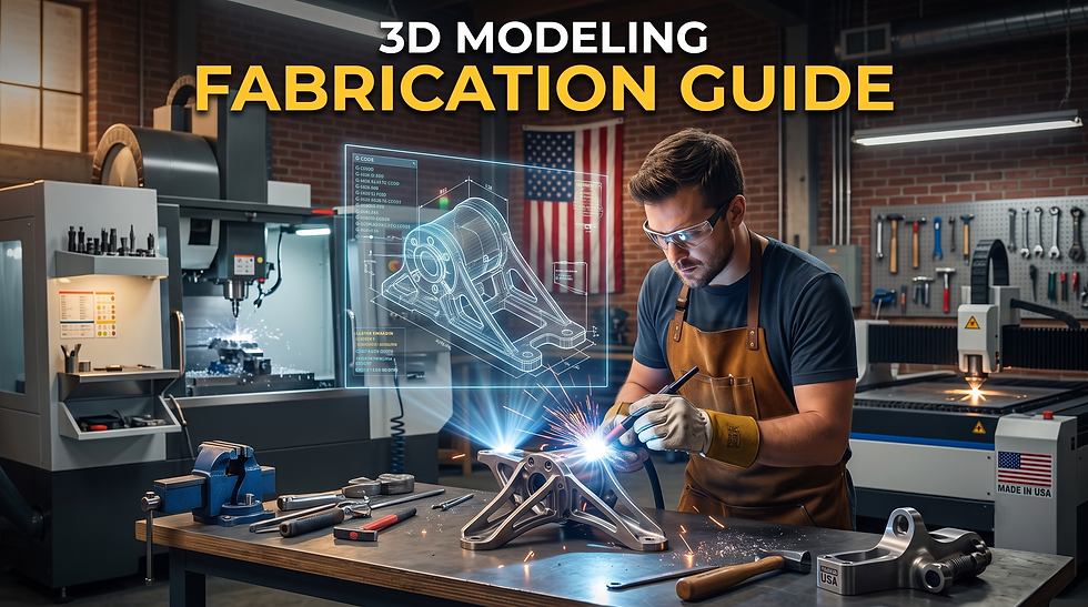
Here's the thing about custom fabrication. The gap between an engineering idea and a finished part has shrunk a lot in the last ten years. But for US fabrication shops, one factor still decides how smooth that journey is: the quality of 3D modelling for custom fabrication and the 2D production draftings that come out of it.
Get the model right and the shop floor barely has to think twice. Get it wrong, and you're looking at RFIs, re-work, and a client losing patience with every extra week added to the schedule.
This post is written for manufacturing engineers, fabrication shop owners, and product development managers who commission this work, either through an in-house team or an outsourced partner. Custom fabrication CAD draftings sit right at the center of that decision. So let's break down what actually separates a smooth job from a messy one.
Why the Model Quality Decides Everything on the Shop Floor
Look, a good 3D model isn't just a pretty rendering on a screen. It has to be parametrically sound, so design changes don't break the whole file when someone tweaks a hole pattern. It needs dimensions that are complete, not scattered across three different revisions.
And it needs GD&T callouts that actually reflect what the manufacturing process can hold, not textbook tolerances copied from an old template.
When 3D model to fabrication handoffs go well, the machinist or welder can work with minimal interpretation. They don't call the engineer asking what a dimension means.
They don't guess at a surface finish because the note is missing. Good 3D modelling for custom fabrication treats the model as a production document, not a design sketch. That mindset shift alone fixes half the problems we see.
The Real Cost of Getting Custom Fabrication It Wrong
We see this pattern again and again with our students and with shops we've worked alongside. A first article gets rejected on the inspection table. Someone has to figure out why, and that eats a full day at minimum.
First, wrong nominal dimensions on the model, sometimes one typo carried through three revisions. Second, GD&T callouts on the drafting that are missing or set too tight for the process to hold. Third, a surface finish note on the drafting that doesn't match the model. Fourth, a BOM line that doesn't match what's in stock.
Every one of these looks small on its own. But stack a few together, and you've got schedule delays and margin loss that's hard to explain to the client. Custom fabrication CAD draftings that skip any of these checks end up costing more later, not less.
From Concept to Shop Floor: The Production Workflow
Bottom line, the workflow matters as much as the software you're using. Concept geometry usually starts in SolidWorks or Inventor. That's where parametric constraints get built in, so the design can iterate without a full rebuild every time someone changes a bolt pattern or a wall thickness.
From there, drafting production takes over. This is where dimensional annotation gets completed in full, GD&T gets applied per ASME Y14.5, and weld symbols follow AWS A2.4 so the welder isn't guessing at joint prep on the shop floor. SolidWorks fabrication draftings that follow this sequence tend to sail through first article inspection without much of a fight.
A clean 3D model to fabrication handoff also means fewer phone calls between the shop and the design team mid-build. And the BOM can't be an afterthought tacked on at the end. It has to integrate cleanly with the client's ERP or procurement system, or you'll get mismatched material specs showing up right when the job is already on the floor and time is tight.
This is the part of 3D modelling for custom fabrication that separates a rushed job from one that's actually built to run smoothly.
Different Fabrication Jobs Need Different Drafting Types
Not every job needs the same drafting package, and treating them all the same is a mistake. Machined components need tight dimensional call-outs and tolerance stacks that respect the machine's actual capability, not just the drawing's intent. Weldment assemblies need clear weld symbol placement and joint details that a welder can read at a glance.
Sheet metal work needs accurate flat patterns, because a flat pattern that's off by even a degree throws the whole bend sequence out of alignment. Structural steel jobs need member details that a fabricator can read fast, without flipping through five different sheets to find one dimension. Even here, SolidWorks fabrication draftings built with consistent layer standards make the shop's job noticeably easier.
And custom enclosure fabrication packages need CNC-ready 3D models that go straight into the machine without extra cleanup work. Getting the drafting type right for the job, not just technically correct on paper, is half the battle in custom metal fabrication draftings. SolidWorks fabrication draftings built with this in mind save the shop floor real time, job after job.
Building Design for Manufacturability Into the Process
Our students often ask why a DFM review matters if 3D modelling for custom fabrication already looks correct on screen. Here's the answer: a model can be dimensionally perfect and still be a nightmare to machine or weld in practice. A DFM review catches that early, before it turns into a shop floor problem that costs real money.
Tolerance stack-up analysis is part of this too, and it matters just as much for custom metal fabrication draftings as it does for machined parts. It's not glamorous work, but skipping it is exactly how you end up with parts that don't assemble on the first try. And when engineering changes happen, and they always do at some point, a clean engineering change order process keeps the whole 3D modelling for custom fabrication workflow from falling apart mid-project.
Custom metal fabrication draftings that build in this discipline from day one avoid most of the rework that eats into a shop's margin.
Why More US Manufacturers Are Outsourcing This Work
Keeping a full-time in-house team for 3D modelling for custom fabrication is expensive, plain and simple. Skilled CAD drafters aren't easy to find, and workloads swing up and down hard depending on where a company sits in its project pipeline. That's why more US manufacturers and fabrication shops are turning to outsourced drafting partners instead of hiring internally.
This is where a team like PrimaVerse fits into the picture. PrimaVerse works as a production partner for manufacturers who need consistently shop-floor-ready 3D models and fabrication draftings, without carrying the overhead of a full in-house team.
Whether it's custom fabrication CAD draftings for a one-off prototype or CNC-ready 3D models for a recurring production run, the goal stays the same. Draftings that a shop can pick up and run with, first time round, no back and forth needed.
Wrapping Up
3D modelling for custom fabrication isn't just a design step you rush through to get to production faster. It's the foundation that decides whether your first article passes inspection or gets sent right back to the drawing board. Get the model right, get the GD&T right, and keep the BOM in sync, and the shop floor gap closes on its own without anyone forcing it. Shops that standardize around CNC-ready 3D models from the start tend to see this play out fastest, job after job.
If you're a manufacturing engineer or a shop owner tired of RFIs eating into your schedule, it might be time to look at how your 3D model to fabrication process actually works, start to finish. Sometimes the fix isn't a new machine on the floor. It's a cleaner model.
FAQs
1. What is 3D modelling for custom fabrication?
It means building a digital model of a part before it gets made on the shop floor. The model carries every dimension, tolerance, and material note the fabricator needs. A good one removes guesswork from the build.
2. Why does 3D model quality matter so much in custom fabrication?
Because the shop floor works directly from that model, not from the engineer's intent. If the model has wrong dimensions or missing GD&T, the part gets built wrong the first time. That means rework, wasted material, and a delayed delivery.
3. What is the difference between a 3D model and a fabrication drafting?
The 3D model is the digital geometry. The fabrication drafting is the 2D document derived from it, showing dimensions, tolerances, weld symbols, and notes the shop actually reads. Both need to match exactly, or the shop gets conflicting information.
4. What causes most first article rejections in custom fabrication?
Usually one of four things. Wrong nominal dimensions, GD&T that does not match the process capability, a surface finish note that does not match the model, or a BOM entry that does not match what is stocked. Catching these before the job hits the floor saves real money.
5. Which software is best for custom fabrication CAD draftings?
SolidWorks and Inventor are the two most common choices in the US fabrication industry. Both handle parametric modelling well, which lets a design change without a full rebuild. The right choice usually comes down to what the shop and client already use.
6. What is GD&T and why does it matter for fabrication drafting?
GD&T stands for Geometric Dimensioning and Tolerancing. It tells the shop exactly how much variation is acceptable on a feature, based on function, not guesswork. Fabrication drafting done per ASME Y14.5 keeps this consistent across the whole job.
7. How do CNC-ready 3D models speed up fabrication?
A CNC-ready model has clean geometry that goes straight into the machine without extra cleanup. This cuts down programming time and reduces the chance of an error creeping in during file conversion. It matters most for enclosure work and repeat production runs.
8. Why do manufacturers outsource 3D modelling and fabrication drafting?
A full in-house team is expensive and hard to staff consistently. Workloads also swing hard depending on the project pipeline. A dedicated drafting partner gives shop-floor-ready output without that overhead sitting on the books year round.
9. What is design for manufacturability and why does it matter in fabrication?
DFM is a review step that checks whether a model can actually be built the way it looks on screen. A part can be dimensionally correct and still be a pain to machine or weld. DFM catches that early, before it turns into a shop floor problem.
10. How does tolerance stack-up analysis affect a fabrication project?
It checks how small tolerances on individual parts add up across an assembly. Skip it, and parts that look fine on paper often won't fit together on the floor. Not glamorous work, but it prevents some of the costliest rework in custom fabrication.


Comments